Leave Your Message
banner_21

How to Choose the Right 3 Axis Load Cell in 2026?

Choosing the right 3-Axis Load Cell in 2026 requires more than comparing capacity, price, and datasheet accuracy. The sensor must match the real forces acting on your equipment. A robotic gripper may experience vertical load, side pressure, and twisting at the same moment. A test fixture may face vibration, shock, temperature changes, and uneven mounting. Small installation mistakes can create large measurement errors.

Dr. Stefan Schmidt, a force-measurement specialist, explains, “The quality of a measurement begins with the mechanical setup.” That principle remains highly relevant. Before selecting a 3-Axis Load Cell, engineers should define the force range on each axis, expected overload, resolution, stiffness, operating temperature, and signal interface. Pay attention to cross-talk. A force applied on one axis should not produce a misleading response on another. Review calibration data, environmental ratings, connector protection, and the supplier’s technical support history. Trustworthy manufacturers should provide traceable calibration information and clear application guidance.

Real-world experience also matters. A sensor rated for 1,000 newtons may appear suitable, yet repeated impacts can shorten its service life. A compact model may fit the machine but lack enough overload protection. These details are easy to miss. Sometimes, the “best” sensor is not the most accurate one. It is the one that remains stable after thousands of cycles, cable movement, and imperfect alignment. This guide examines those practical decisions for 2026. It also acknowledges an uncomfortable truth: specifications alone cannot predict every field condition. Careful testing is still necessary.

How to Choose the Right 3 Axis Load Cell in 2026?

What a 3 Axis Load Cell Measures and How It Works

How to Choose the Right 3 Axis Load Cell in 2026?

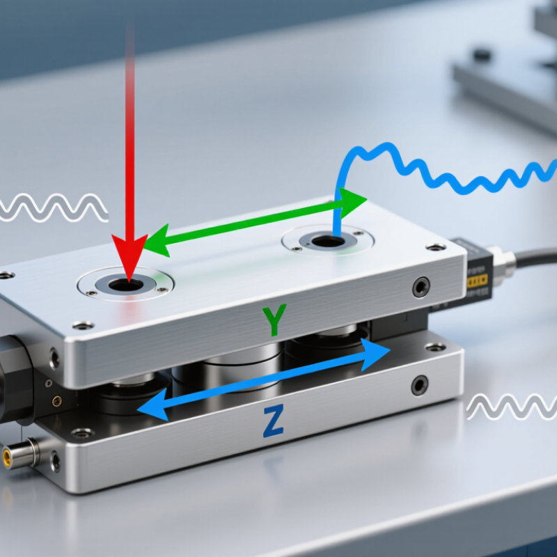
A 3 axis load cell measures force along three perpendicular directions: Fx, Fy, and Fz. Fx and Fy describe side loads, while Fz records compression or tension. Inside, bonded strain gauges deform slightly when force reaches the sensing structure. A Wheatstone bridge converts that deformation into an electrical signal. The change is tiny. Signal conditioning makes it usable.

This matters in robotic gripping, assembly checks, medical equipment, and material testing. The 2024 World Robotics report recorded 541,302 industrial robot installations worldwide in 2023. More robots mean more demand for reliable multi-directional force feedback. Yet one axis rarely tells the whole story. A gripper may press downward while sliding sideways. A single-axis sensor can miss that interaction.

When choosing a sensor, check rated force, overload capacity, sensitivity, cross-talk, sampling rate, and temperature drift. ISO 376 calibration practices emphasize traceability and measurement uncertainty. Ask for calibration data, not only a headline accuracy figure. Test the sensor under combined loads, because real forces rarely arrive neatly. A high rating is not always better. It can reduce resolution. Installation stiffness also matters; a flexible mount may distort the result. I have seen specifications look excellent on paper, then weaken after cable movement and thermal changes. That is an uncomfortable reminder. Selection should include field testing, although many projects underfund it.

How to Choose the Right 3 Axis Load Cell in 2026?

A 3-axis load cell measures force independently along three perpendicular axes: X, Y, and Z. The chart shows a representative force profile from a 10-second test, with the vertical preload on the Z-axis and lateral forces on the X- and Y-axes.

How it works: Internal strain-sensitive elements deform slightly when force is applied. The resulting electrical signals are converted into signed force values in newtons (N). When selecting a load cell, check the expected peak force on each axis, the combined resultant force, overload protection, resolution, and the required measurement frequency.

Example: The plotted profile reaches approximately 42 N on X, −16 N on Y, and 120 N on Z. Its combined peak force is about 128 N, so the selected sensor should have a suitable margin above this calculated load and any expected shock loads.

Key Specifications to Compare Before Choosing a Model

How to Choose the Right 3 Axis Load Cell in 2026?

Choosing a 3 axis load cell starts with the forces your application actually produces. Measure compression, tension, and shear separately, then record their peak values. Do not size the sensor only from average loads. Sudden impacts can exceed them quickly. A safety margin is necessary, but excessive capacity may reduce measurement resolution.

Compare rated capacity, accuracy, sensitivity, nonlinearity, hysteresis, and repeatability. Check cross-talk between axes, especially when forces occur together. A sensor may perform well on one axis but drift during combined loading. Review excitation voltage, output signal, insulation resistance, and temperature compensation. Environmental ratings also matter. Dust, moisture, vibration, and repeated cleaning can change field performance. Confirm the mounting pattern and available space before ordering. I have seen good sensors fail because the fixture introduced bending.

Tips: Test the complete assembly, not just the sensor. Use calibration data from realistic load directions. Ask for overload limits and temperature curves. Check cable routing near moving parts. Short cables are not always better. Record zero drift after warm-up, because early readings can be misleading. If your forces are uncertain, document that uncertainty instead of hiding it. A careful engineer should challenge the original load estimate. Calibration should be traceable to recognized standards, with test conditions clearly recorded. Reliability comes from both specification review and practical verification.

How to Match Load Cell Capacity to Your Application

How to Choose the Right 3 Axis Load Cell in 2026?

How to Match Load Cell Capacity to Your Application

Select a 3 axis load cell by matching capacity to the largest expected force on each axis. Start with the load. Record vertical force, side force, torque, impact, and repeated cycles. A machine may appear light during normal operation, yet acceleration can create sharp load peaks.

Do not size the sensor from the average reading alone. Use measured peak values, then add a practical safety margin, often between 20% and 50%. The correct margin depends on shock, vibration, mounting accuracy, and test frequency. Too little margin risks overload. Too much reduces sensitivity and hides small changes. That trade-off matters.

For dynamic equipment, capture real signals with a calibrated instrument before choosing capacity. For example, a gripper lifting 80 newtons may generate 130 newtons during sudden stops. Selecting a 150-newton range could work, but it leaves limited room for errors. A 200-newton range may offer safer operation, although resolution could suffer.

Check each axis separately. One axis may need high capacity while another requires fine measurement. Also review overload ratings, temperature drift, humidity, cable movement, and mounting stiffness. Real installations rarely behave like laboratory drawings. I have seen flexible brackets distort readings more than the load cell itself. A spreadsheet helps, but field testing remains essential.

Recheck the decision after installation. Compare predicted forces with recorded peaks, then revise the safety factor if necessary. Capacity should protect the sensor without wasting measurement detail. That balance is easy to miss.

Environmental, Mechanical, and Electrical Compatibility Factors

How to Choose the Right 3 Axis Load Cell in 2026?

Environmental, Mechanical, and Electrical Compatibility Factors

A 3 axis load cell must survive the environment around it, not just measure force accurately. Check temperature range, humidity, dust, vibration, and cleaning exposure. Outdoor equipment may need sealed construction and corrosion-resistant materials. Indoor machinery can still face condensation near cooling systems. I have seen accurate sensors drift after repeated temperature changes. That detail is easy to underestimate.

Mechanical compatibility starts with load direction, capacity, mounting space, and expected overloads. Select separate ratings for X, Y, and Z forces when the application is uneven. Confirm thread sizes, mounting surfaces, cable routing, and alignment tolerances. A small installation error can create unwanted side loads. Do not rely only on a product drawing. Measure the actual structure, including washers and fasteners. The frame may flex.

Tips: Test the sensor under real operating conditions. Apply known loads in each axis, then record zero drift and cross-talk. Check whether nearby motors or long cables introduce electrical noise. Match the excitation voltage, output signal, bridge resistance, amplifier range, and connector protection. Shielded cables help, but grounding mistakes can still damage signal quality. Keep a calibration record. Recheck it after impact, overload, or major maintenance, because assumptions often age badly.

Installation, Calibration, and Long-Term Performance Checks

Choosing the right 3 Axis Load Cell in 2026 requires more than checking capacity and price. Installation quality strongly affects every measurement. Mount the sensor on a rigid, level surface with a clear load path. Avoid side forces, cable tension, and loose fasteners. Keep cables away from motors and high-current wiring. A small alignment error can create large cross-axis readings.

Calibration should match the real working range, not only the maximum rated load. Use traceable reference weights or a certified force system. Apply loads separately along each axis, then repeat combined loading when possible. Record zero output, sensitivity, and temperature during testing. I once trusted a stable zero too quickly. A later temperature change revealed mounting stress. That mistake changed my inspection routine.

Check performance during normal operation. Compare daily zero values, axis balance, and signal noise against the original commissioning record. Inspect seals, connectors, mounting bolts, and cable jackets for moisture or wear. Review the data after heavy impacts or unusual temperature cycles. Schedule verification at intervals based on usage, environment, and risk. Shorter intervals are sensible in dusty or vibrating locations. Long-term drift may appear slowly. Watch the trend. A clean spreadsheet can hide a poor test method, so repeat questionable measurements before adjusting the system.

How to Choose the Right 3 Axis Load Cell in 2026? - Installation, Calibration, and Long-Term Performance Checks

Selection or Check Area Key Dimension Recommended Technical Data Installation or Test Method Typical Acceptance Criteria Suggested Frequency
Application Definition Measured force components Three independent channels: Fx, Fy, and Fz. Select a sensor that matches the actual direction and combination of forces. List the maximum, minimum, static, dynamic, shock, and reversing loads expected in normal operation. Rated capacity should exceed the highest continuous working load while leaving sufficient margin for overloads and transients. Before selection and after major process changes
Capacity Selection Rated load and overload protection Choose separate capacity ratings for each axis where available. Avoid operating continuously near the rated limit. Compare the complete load envelope, including combined-axis loading and accidental impact loads, with the sensor specification. Normal operation remains within the manufacturer’s stated rated range; overload stops or mechanical protection are used where required. Design review and annual verification
Resolution Signal resolution and noise Resolution should be at least 5 to 10 times finer than the smallest force change that must be detected. Measure the zero output with the system unloaded and record peak-to-peak noise over a representative time period. Noise is small enough that the required measurement resolution is not obscured; filtering does not hide relevant transient events. Commissioning and quarterly monitoring
Combined Loading Cross-talk between axes Use the specified cross-axis sensitivity, commonly expressed as a percentage of the applied load or full scale. Apply a known force to one axis while measuring the output of the other two axes. Repeat for Fx, Fy, and Fz. Measured cross-talk is within the sensor specification and remains stable compared with the original calibration record. Initial calibration and after overload or mechanical impact
Mechanical Installation Mounting surface and alignment Use rigid, flat, clean mounting surfaces and the correct bolt grade, thread engagement, and tightening torque. Check surface flatness, remove burrs, align the sensing axes with the application coordinate system, and tighten fasteners in a controlled sequence. No visible rocking or gap; axis misalignment is within the application tolerance, typically no more than about 0.5° for precision work. Installation, relocation, and annual inspection
Load Introduction Force path and parasitic loads Loads should enter through the intended interface without unintended bending, torsion, cable pull, or side loading. Inspect adapters, brackets, bearings, and flexures. Confirm that cables are strain-relieved and cannot transmit force to the sensor. Force is applied through the designed load path; cable movement and fixture friction do not produce measurable output changes. Installation and whenever fixtures are changed
Environmental Suitability Temperature, moisture, and contamination Confirm the operating temperature range, temperature compensation, ingress protection, chemical compatibility, and cable rating. Install shielding, sealing, drainage, or environmental protection when exposed to washdown, dust, oil, condensation, or temperature cycling. The actual environment remains within the specified limits, and no moisture ingress, corrosion, or insulation deterioration is present. Continuous monitoring; visual inspection monthly or per risk level
Electrical Installation Excitation, grounding, and shielding Use the required excitation voltage or current, compatible input impedance, shielded cable, and suitable signal conditioning. Verify polarity, connector pinout, supply stability, grounding, cable routing, and separation from motors, relays, and high-current conductors. Supply remains within the specified tolerance; no unexpected zero drift, electrical interference, or intermittent channel dropout occurs. Commissioning and after electrical modifications
Warm-Up Thermal stabilization Allow the sensor and signal conditioner to reach a stable temperature before precision measurements. Power the system for approximately 15 to 30 minutes, or for the period established during validation, with no applied load. Zero readings stabilize within the project-defined limit before calibration or production measurement begins. At startup and after significant temperature changes
Zero Balance Unloaded output of Fx, Fy, and Fz Record zero values for all three channels at the normal operating temperature and fixture condition. Remove all external loads, wait for mechanical settling, and capture multiple zero readings rather than relying on one sample. Zero offset is within the sensor specification and does not show unexplained step changes or progressive drift. Before each critical test; daily for high-accuracy applications
Calibration Multi-axis calibration procedure Calibrate each axis independently and verify representative combined-load cases when the application uses simultaneous forces. Use traceable reference equipment with adequate capacity and accuracy. Apply increasing and decreasing loads at defined points and document the sequence. Indicated values meet the required accuracy, repeatability, hysteresis, and linearity limits for the application. At commissioning, typically every 6 to 12 months, or by risk-based interval
Reference Standards Traceability and uncertainty Reference loads should be traceable to a recognized national or international measurement standard. Maintain calibration certificates for reference instruments and include the measurement uncertainty in the calibration report. Calibration uncertainty is suitably lower than the allowable error of the 3-axis measurement system. Review at every calibration cycle
Data Acquisition Sampling rate and filtering Set the sampling rate high enough to capture the fastest event of interest; avoid excessive filtering that removes valid load changes. Validate sample rate, anti-alias filtering, digital filtering, channel synchronization, units, scaling, and time stamps. All three channels are synchronized and the recorded waveform represents the application’s relevant force dynamics. Commissioning and after software or hardware changes
Repeatability Repeated load response Use the same fixture, loading point, direction, and loading rate for repeatability checks. Apply the same known load several times and compare the indicated values after unloading and reloading. Variation is within the application tolerance and does not increase significantly over successive cycles. Monthly, quarterly, or according to process criticality
Hysteresis Increasing versus decreasing load output Evaluate the difference between readings taken at the same load during loading and unloading. Run a controlled loading cycle across the intended measurement range and compare corresponding points. Hysteresis remains within the stated sensor or project specification; sudden changes may indicate fixture friction or overload damage. During scheduled calibration
Long-Term Drift Zero and sensitivity stability Trend zero balance, span response, cross-talk, temperature, and calibration residuals over time. Use control charts or a digital maintenance log with the same reference load and test conditions whenever possible. Trend remains stable; investigate gradual drift, abrupt shifts, increasing noise, or channel-to-channel disagreement. Each verification cycle; review at least quarterly
Overload and Shock Post-event inspection Any overload, impact, dropped fixture, or unexpected machine collision should be treated as a potential calibration event. Inspect the structure and connectors, repeat zero and reference-load checks, and recalibrate if results have changed. No permanent deformation, cracked housing, damaged cable, unstable zero, or abnormal cross-talk is observed. Immediately after an overload or shock event
Maintenance Records Configuration and history Maintain sensor identification, installation orientation, capacity, wiring, calibration coefficients, test conditions, and service history. Store raw readings, environmental conditions, fixture details, operator, date, reference equipment, and corrective actions. Each result is traceable to a specific sensor, setup, software configuration, and reference standard. Every inspection, calibration, repair, or configuration change
Replacement Decision End-of-life indicators Consider replacement when performance cannot be restored through approved calibration, repair, or fixture correction. Compare current results with historical records and assess drift, noise, insulation, mechanical condition, and calibration uncertainty. Replace the sensor if it repeatedly fails acceptance limits, shows structural damage, suffers unstable output, or no longer meets measurement risk requirements. After failed verification and during annual asset review