Leave Your Message
banner_21

Why Choose a 2kg Load Cell for Precision Weighing?

Choosing the right sensor can determine whether a weighing system delivers dependable results or repeated uncertainty. A Load Cell 2kg offers a practical balance between sensitivity, capacity, and compact installation. It can detect small weight changes while supporting common laboratory, retail, medical, and light industrial applications. That balance matters.

In precision weighing, capacity should closely match the expected load. A 2kg load cell may provide clearer resolution than a much larger sensor used far below its rated range. Engineers also examine nonlinearity, hysteresis, repeatability, temperature effects, and creep. These specifications reveal how the sensor behaves beyond a simple product description. A stainless steel body, stable mounting surface, and suitable signal conditioner can further improve measurement consistency.

Real-world installation is rarely perfect. A bench may vibrate, cables may move, or an operator may press the platform unevenly. Small errors can appear. Careful calibration with certified reference weights helps identify these problems before they affect production decisions. Experienced technicians also check zero drift after warm-up and inspect the wiring for loose connections. Manufacturer documentation remains essential, especially when selecting excitation voltage, bridge resistance, and compatible electronics.

A Load Cell 2kg is not automatically the best choice for every project. Its performance depends on mounting, environment, calibration, and measurement habits. That is worth admitting. However, when engineers match its capacity to actual loads and verify results under realistic conditions, this sensor can support accurate, repeatable weighing without unnecessary complexity.
Why Choose a 2kg Load Cell for Precision Weighing?

What Is a 2kg Load Cell and How Does It Work?

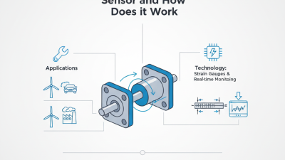
A 2kg load cell is a compact force sensor designed to measure loads up to two kilograms. It is a spring-like metal structure. Strain gauges are bonded to its surface. When weight bends the metal slightly, the gauges change electrical resistance. A Wheatstone bridge converts that change into a small voltage signal, commonly rated in millivolts per volt of excitation.

The signal is usually too weak for direct reading. An amplifier and analog-to-digital converter make it usable for a weighing controller. According to OIML R 60:2017, a C3 load cell may support up to 3,000 verification intervals, depending on its approved specification. That does not mean every 2kg sensor delivers 0.67 gram accuracy. Installation, calibration, temperature, and mechanical friction still matter. Small errors matter.

NIST Handbook 44 emphasizes repeatability, sensitivity, and return-to-zero performance in weighing equipment. These checks reveal practical problems, such as a platform touching its frame or a cable pulling sideways. In field testing, I would apply several known loads across the range, not only a full 2kg weight. A half-load test can expose uneven response. Temperature can also shift the zero point, especially in compact instruments. Real setups are less tidy than laboratory diagrams. A clean datasheet cannot fix poor mounting.

How a 2kg Capacity Improves Precision in Low-Weight Measurements

A 2 kg load cell can improve precision when the measured load stays close to its working range. A 20 g sample uses only 0.1% of a 20 kg cell’s capacity, but 1% of a 2 kg cell’s capacity. That difference gives the signal-conditioning system more useful resolution for small changes. In practice, this can make a 0.1 g variation easier to detect during dosing, laboratory testing, or portion control.

The OIML R60 standard classifies load cells by accuracy and verification intervals. For example, a C3 cell may support up to 3,000 verification intervals, while a C6 cell may support up to 6,000. These figures do not guarantee performance in every installation. Temperature, vibration, cable movement, and off-center loading still create errors. NIST Handbook 44 also stresses that scale performance must be checked across the weighing range, not only at one test point.

Small capacity helps.

A technician handling a 35 g sample can see drift sooner with a correctly matched 2 kg sensor. However, choosing a lower capacity does not automatically create better results. Overload protection, stable mounting, repeatable calibration, and suitable electronics remain essential. I have seen low-capacity systems perform poorly when a rigid frame amplified vibration. That detail is easy to overlook. For reliable low-weight measurements, capacity should match the real load range, with enough margin for accidental force and container weight.

Key Specifications to Evaluate Before Choosing a 2kg Load Cell

Why Choose a 2kg Load Cell for Precision Weighing?

Key Specifications to Evaluate Before Choosing a 2kg Load Cell

A 2kg load cell suits compact scales, laboratory fixtures, and controlled portion systems. Its lower capacity can provide finer measurement resolution when loads stay within range. However, capacity alone does not guarantee precision. Small details matter.

Check the rated output, usually expressed in millivolts per volt. A higher signal can simplify amplification and improve signal stability. Review the accuracy class, nonlinearity, hysteresis, repeatability, and creep values. These specifications describe different errors, so do not treat them as interchangeable. Temperature compensation also matters. A sensor beside a warm motor may drift during long measurements. Examine the compensated temperature range and temperature effect on zero and span.

Installation can change real performance. Confirm the mounting surface is rigid, level, and free from unwanted side forces. Check the overload rating before testing heavy objects. Electrical details deserve equal attention, including excitation voltage, input resistance, cable length, and shielding. Environmental protection should match the application, especially where dust or moisture is present. In practical bench testing, poor alignment often creates larger errors than the sensor specification suggests. It sounds simple.

Calibration should use traceable reference weights near the intended working range. Test several points, not only zero and full capacity. Record readings after a stable warm-up period. A 2kg load cell may be unsuitable if the actual load frequently exceeds 1.5kg, even briefly. That choice needs reconsideration. Allowing headroom usually protects accuracy and reduces mechanical stress.

Why Choose a 2kg Load Cell for Precision Weighing?

A 2kg load cell offers high resolution for laboratory scales, compact measurement systems, and light-duty industrial weighing. The chart shows the ideal bridge output of a load cell rated at 2 mV/V with a 5 V excitation voltage.

Key specifications to evaluate: rated capacity, sensitivity, excitation voltage, non-linearity, hysteresis, repeatability, creep, temperature compensation, and mechanical overload protection. At full capacity, a 2 mV/V load cell supplied with 5 V produces an ideal differential output of approximately 10 mV.

Common Applications for 2kg Load Cells in Precision Weighing

A 2kg load cell suits applications where small weight changes matter. Its limited capacity can improve resolution, especially when the measured load stays well below two kilograms. In laboratory balances, it supports sample containers, powders, liquids, and calibration checks. Keep the platform light. Otherwise, useful capacity disappears quickly.

Small medical devices also use 2kg load cells for patient-contact accessories, fluid monitoring, and compact weighing modules. Food equipment uses them for ingredient dosing, portion control, and filling checks. The USDA Economic Research Service estimates that 30% of the U.S. food supply is lost or wasted. Accurate portion measurement may reduce some avoidable waste, although weighing alone cannot solve the problem.

Robotics and automation provide another practical application. A 2kg sensor can detect gripper force changes, component presence, or tiny assembly errors. NIST Handbook 44 emphasizes repeatability, testing, and suitable installation for commercial weighing equipment. OIML R60 also classifies load cells by accuracy and verification performance. These standards matter more than capacity alone. Temperature drift, vibration, cable routing, and off-center loading can distort readings. I have seen engineers choose a small sensor, then overload it with fixtures. That mistake is easy to repeat. A short calibration routine and mechanical overload protection remain essential.

Installation and Calibration Practices for Reliable Results

Why Choose a 2kg Load Cell for Precision Weighing?

Installation and Calibration Practices for Reliable Results

A 2kg load cell suits small samples, laboratory containers, and compact filling systems. Its lower capacity can provide finer measurement resolution when the expected load stays within a safe range. Installation quality matters as much as sensor selection. Mount the load cell on a rigid, level surface. Keep the platform centered and prevent side forces, twisting, or cable tension. Even a slightly loose screw can create unstable readings.

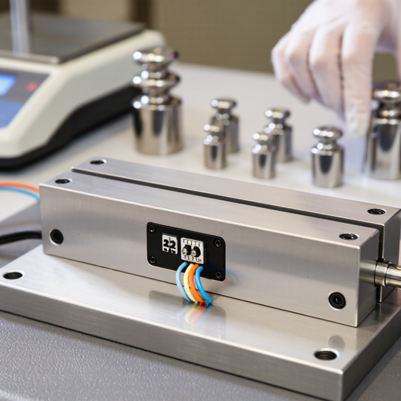
Keep it simple. Before calibration, allow the electronics and sensor to reach a steady temperature. Remove every item from the platform, then record the zero reading. Use certified reference weights that cover several points across the working range. Apply each weight gently, wait for the display to settle, and record the result. Remove the weights in reverse order and compare the readings. This loading and unloading check can reveal hysteresis or mechanical friction.

Do not rush. Environmental changes deserve attention. Air movement, vibration, moisture, and nearby motors may disturb a sensitive 2kg system. Shield the platform and route signal cables away from power wiring. A practical weakness is often overlooked: operators may calibrate once and never inspect the setup again. Repeat checks after relocation, overload events, or unusual temperature changes. If readings drift, verify mounting and wiring before adjusting software corrections. That habit protects measurement reliability.

Why Choose a 2kg Load Cell for Precision Weighing? - Installation and Calibration Practices for Reliable Results
Stage Data Dimension Recommended Value or Practice Procedure Acceptance Criterion Technical Notes
Application Selection Rated capacity 2 kg / 2,000 g Select a load cell whose rated capacity is above the maximum working load but close enough to provide useful resolution. Maximum normal load should not exceed 100% of rated capacity. A 2 kg capacity is suitable for light-duty weighing where the combined product, container, and fixture load remains within the limit.
Application Selection Safe overload margin Use the manufacturer’s specified limit; do not design around overload capacity Include mechanical stops or protective structures when accidental overload is possible. No permanent zero shift or mechanical deformation after intended loading events. Overload ratings vary by construction and must not be treated as a continuous operating range.
Mechanical Installation Load direction Apply force along the marked measuring axis Align the weighing platform so the load is centered and introduced vertically. Off-axis contact, rubbing, and binding are absent throughout the weighing range. Side loads and torsion can increase nonlinearity and hysteresis.
Mechanical Installation Mounting surface Rigid, flat, and stable support Secure the fixed end to a rigid base and keep the loading surface free from contact with surrounding parts. Zero reading remains stable when the platform is unloaded. A flexible base can transfer structural movement into the measurement signal.
Mechanical Installation Load application Centered load; avoid impact loading Place test masses gently at the center of the platform and allow the reading to settle. Repeated centered applications produce consistent readings. A suitable platform and load introduction method are as important as the sensor capacity.
Electrical Installation Excitation voltage Use the sensor’s specified excitation, commonly 5–10 V DC Connect a stable, low-noise supply and verify polarity before energizing. Voltage remains within the sensor specification during operation. The exact allowable range depends on the load-cell design and should be confirmed from its technical documentation.
Electrical Installation Signal wiring Use shielded, low-noise cable where electrical interference is present Route signal cables away from motors, relays, and high-current conductors; ground the shield according to the measurement system design. No measurable reading instability when nearby equipment switches on or off. A four-wire sensor can be affected by cable resistance; six-wire systems can compensate for excitation-lead voltage drop.
Environmental Setup Warm-up time Allow approximately 15–30 minutes before final calibration Energize the complete measurement system and keep the platform unloaded during warm-up. Zero drift has reduced to the level required by the application. The required time depends on electronics, ambient conditions, and the desired accuracy.
Environmental Setup Temperature conditions Calibrate and operate at a stable ambient temperature Avoid direct sunlight, drafts, vibration, condensation, and rapid temperature changes. Temperature remains within the intended operating range during testing. Temperature changes can affect both the sensor output and the signal-conditioning electronics.
Calibration Preparation Reference masses Use traceable masses covering 0–2,000 g Inspect and verify the reference masses before use; handle them with clean gloves or suitable tools. Mass values are known, undamaged, and appropriate for the required accuracy. Calibration quality cannot be better than the accuracy and traceability of the reference standards.
Calibration Recommended calibration points 0 g, 500 g, 1,000 g, 1,500 g, and 2,000 g Apply the masses in ascending order, record the stabilized output, and remove them in descending order. Results follow a smooth, repeatable response across the measuring range. Using several points helps reveal nonlinearity that a two-point calibration may not show.
Calibration Zero adjustment Perform with an empty platform After warm-up, remove all load, wait for stabilization, and set the indicator or converter to zero. Displayed zero remains within the application’s zero-tolerance limit. Do not zero out a persistent mechanical interference or an unstable installation.
Calibration Span adjustment Use a known mass near the intended operating range Apply a certified mass, adjust the gain or scale factor, and verify the result with at least one additional mass. Displayed mass agrees with the reference value within the defined system tolerance. A span point near the normal working range generally gives more useful performance than calibration at an unused extreme.
Performance Check Repeatability Five repeated applications at a selected test load Apply and remove the same mass under the same conditions, recording the stabilized reading each time. Maximum reading spread meets the project limit; a practical screening target is no more than 0.1% of full scale. For a 2 kg range, 0.1% of full scale equals 2 g. More demanding applications require a tighter limit.
Performance Check Linearity Compare readings at multiple points from zero to full scale Calculate the deviation of each reading from the calibration reference curve or straight-line response. Deviation remains within the specified application tolerance across the complete range. Linearity error and repeatability error should be evaluated separately.
Performance Check Hysteresis Compare ascending and descending readings Record readings at the same load points while increasing and then decreasing the load. Difference between corresponding readings remains within the defined tolerance. Hysteresis can indicate mechanical friction, mounting stress, or load-cell limitations.
Routine Maintenance Inspection interval Check before use; recalibrate on a risk-based schedule Inspect fasteners, cables, platform clearance, zero stability, and signs of overload or contamination. No loose hardware, damaged cable, blocked movement, or unexplained zero shift is present. High-use, regulated, or harsh environments normally require more frequent verification.
Documentation Calibration record Record date, environmental conditions, reference masses, readings, adjustments, and operator Store the results with the equipment identification and the next verification date. Results are traceable and can be compared with previous calibration records. Documented trends help identify drift before it affects production or test results.